Hubless Bicycle wheel

Rat Rod Bikes Bicycle Forum

Help Support Rat Rod Bikes Bicycle Forum:

This site may earn a commission from merchant affiliate links, including eBay, Amazon, and others.
bike2112 said:
Well Done. I think I got the other side figured out. Just kidding. I love how you went with wood to house and hold the innards. Nice and clean.
Thanks , its also pretty lightweight , the only trouble with wood is the precision it can be shaped and the deformation over time , but for a proto , it will do the job :)
 
Hi!
I would like to know if this system works well? I wanna do the same thing but I don't know how, so if it work i will probably copy it
 
Fanchon said:
Hi!
I would like to know if this system works well? I wanna do the same thing but I don't know how, so if it work i will probably copy it
i did not even show the system :wink: but yes hubless wheels work , but not efficiently unless you throw big bills to machine accurate parts
 
yes i know but i was looking just for the front wheel, and it's satisfied me. I will try it by my self and maybe put a little mor money if it really works as i want. Thanks for your help
 
Just from an engineering standpoint, I'm riveted to this one... :wink:
 
Hammond Eggz said:
Just from an engineering standpoint, I'm riveted to this one... :wink:
:? don't expect to much updates , this project is put to side for the moment ...i may build a really good one if i ever get a chance to do what i want in my machinist class , but even then , i dont think there machines can lathe or mill 25"diameter parts :roll:
 
HAHA!!! maybe not in your class, but i hope that it exist, i found another way to make it but i need a part that makes 25"
That's why i prefer yours for the moment
 
Fanchon said:
HAHA!!! maybe not in your class, but i hope that it exist, i found another way to make it but i need a part that makes 25"
That's why i prefer yours for the moment
yes it exist , 25inch diameter is very small in the machinist world .. :wink: http://www.youtube.com/watch?v=QQs61tUNgpU
mine was not so good , the pullys wer made out of junk sk8 wheels on a wood lathe with a cardboard template :? lets just say they were not identical :lol:
i think it would need a harder material to , like nylon ,to reduce the friction , and have more of them , with each one lighter with smaller bearings to make it even more light ...and make a kind of 25"rubber seal like to prevent dust from getting inside ... to much ideas, not enough resources :cry:
 
yes it exist , 25inch diameter is very small in the machinist world .. :wink:
mine was not so good , the pullys wer made out of junk sk8 wheels on a wood lathe with a cardboard template :? lets just say they were not identical :lol:
i think it would need a harder material to , like nylon ,to reduce the friction , and have more of them , with each one lighter with smaller bearings to make it even more light ...and make a kind of 25"rubber seal like to prevent dust from getting inside ... to much ideas, not enough resources :cry:


Have you ever tried hard plastics Like for the parts I saw you built out of wood The plastic is cheap easy to come by and works just like wood but without the draw backs of wood. I plastic smith all the time and as a naturalist and tree hugger I like the idea of reusing plastic in place of all my wood needs.I just joined this sight as I am looking for ideas to build my idea of a hubless trike design. I need a good idea for the drive. I want to build it as a rowwing style trike with out pedals at all if possible. Look for my new thread on this idea I will be adding it in the forums. And I will keep watching your build with antisipation. sorry about my spelling, I have disability.
 
I am starting to build a hub-less bicycle wheel :!: :!:
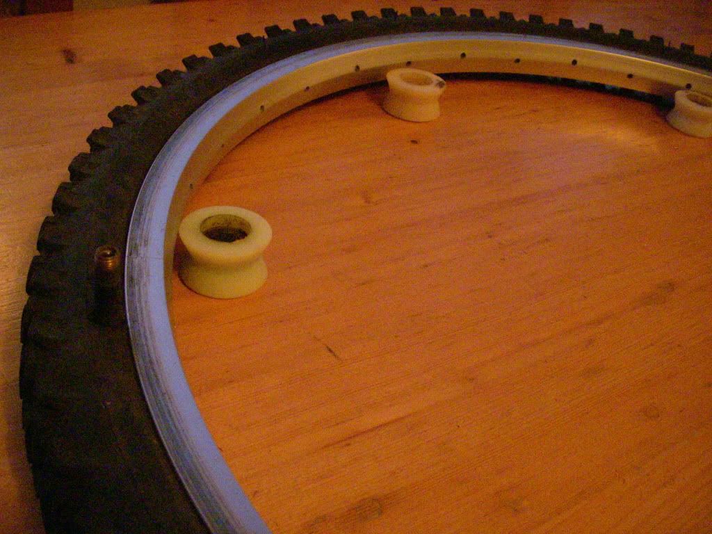
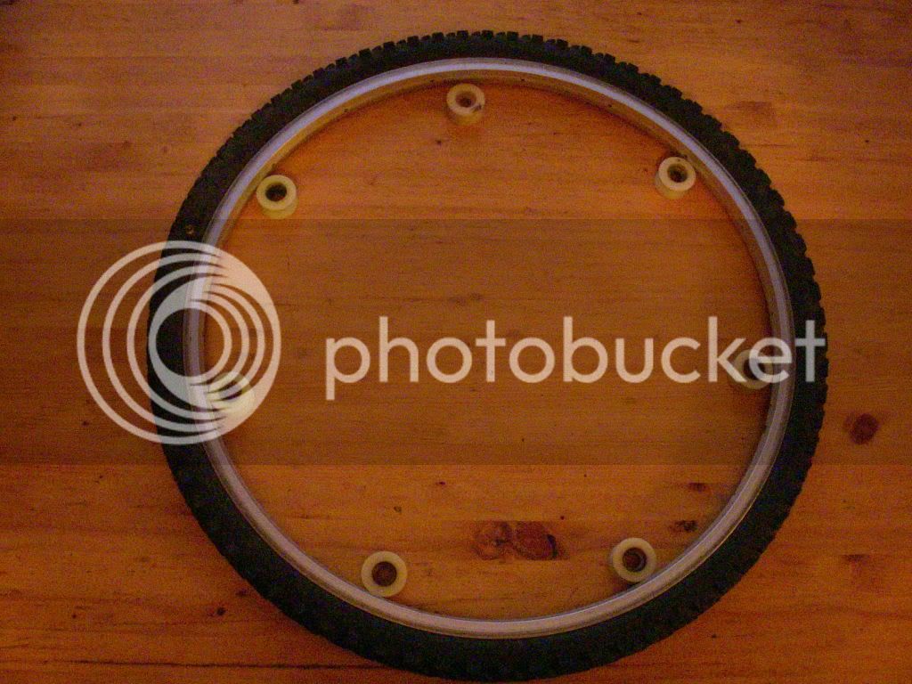
for now i lathe half the small wheels the rim will spin on (made out of old skateboard wheels) and i made a hole in the tire for the valve to be out the way on the rim..
It will be a driving/rear wheel , cause that's the real challenge :mrgreen:
DSCN4988.jpg

DSCN4987.jpg

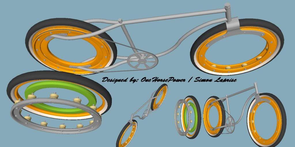
The main problem with a hubless wheel on a bicycle is the gear ratio , but i "invented/find" a new way to do things , so i will post progress , but i may have to get a patent before showing to much :? , its a simple design that use "V" shaped rims and standard tires"modified" ..it will also be possible to get the chain and tire out without having to remove the wheel ,so it will be practicle for maintnance and parts.. i know the friction and weight issues will not be practicle, but this could be fix once the concept is proven to work ..
process could be slow
dude!!! that's an awesome idea.
if you do get into manufacturing these i wanna know.
i would be interested in offering this technology to my customers .
message me and we can discuss the details if you are interested.
Sean
 
Hi guys , its been a while since i posted ... i came back to show you the complete idea, unfortunately it never got built completely and i don't want to spend $$$$$ testing something i don't really need ,so here is the idea
Hublesswheeldesing_zps1689d562.jpg

the pulleys (small wheels) would have small teeth (like soft gears) and are mounted between 2 rings , one of these rings is actually the drive gear for a belt drive(the grey ring in the image) the green ring is the fixed part to the bike frame ,and the orange is a standard strong v shaped rim ... the whole assembly act just like a huge bearing but where the balls(pulley in this case) are what drive the outer wheel/tire . this allow twice less friction and twice the driving ratio of the typical dirrect drive hubless wheels we use to see ... for example picture a wheel rolling on the ground , the ground is traveling 0mph , if the wheel at the axle travel 5mph . the top of the tire actually travels 10mph , feel free to use/build as long as you give a little credit for the idea please.... in reality the frame should have a 1sided mount to the rear wheel to remove the tire quick and ease, and as said in previous post the tire have to be modified with a small hole in the bottom of the side wall just over the rim for the valve to come out
 
Last edited:
With some clever pullies for the drivers, I see a variable speed drive working.
 
Ahhhh, I had that same thought, then realized, "it drives the little wheels/pullies the rim rides on!" Not direct drive on the rim.
 
Hummmm, how to explain...
Ok I got it!
Imagine the center support, round with places for the rollers to go. Put the rollers in place. Then put the drive belt around the rollers, on the outside of them.
Now place the rim assembly over the rollers.
The belt turns the rollers which turn the wheel.
 
OMG@!@!:mad: I been secretly working on the same exact idea basics for 5 years now and Some one just has to be the one to be ahead of me on design...:eek::confused: Well looks like its back to the drawing board. But there is a slight flaw to the designment. What will the braking system be? I been stuck on this for roughly 4 years. I was thinking of using a coaster brake internally fitted into the crank and flush fitting the belt (didn't work)and somehow sleeving the crank arms. Same principal in a way. Or hand operated brakes but the problem I had was the snug fit that interferes with the wheel radius of position of the belt.
 

Latest posts

Back
Top