My wife came back from Afghanistan Friday. Today I had her give me a hand making the suspension/mounting rails for the seat (saddle, if that's your flavor).
Anyone that knows me from other forums will know I typically do detailed, step-by-step builds so those that haven't done what I'm doing can follow along and see how easy this crap can be. All too often people are intimidated by simply thinking that they can't do something. I'm not that type of person. If I want to do it, I can do.
If you want to do it, follow along. :lol:
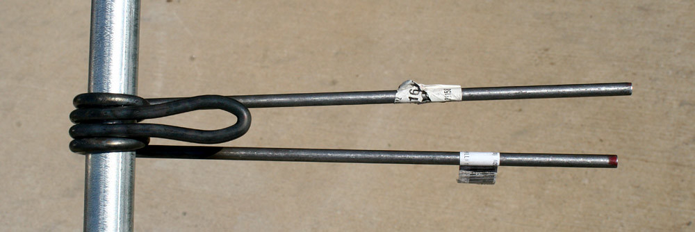
To make this piece I used a 3 ft length of 1/4" steel rod from Lowe's.
Guesstimated the middle of the rod and marked it with a Sharpie, stuck a piece of the rake tooth in the vise, had my wife hold the torch to heat the 1/4" rod, and bent it into a nice U shape around the 1/4" rake tooth. After it cooled I placed the part in the vise and heated both sides of the new part so I could bring the two lengths of rod together and still allow room for the mounting bolt (and a bit of room for the unit to slide fore/aft).
After careful heating of each side and tightening of the vise I was left with this. The two Sharpie marks are to locate the starting point for the next series of bends.
With the main mounting point out of the way it was time to work my way through the part. To get the unit to function like it should I needed it to coil properly. A simple corkscrew like what was on the rake teeth I had bought wasn't going to cut it.
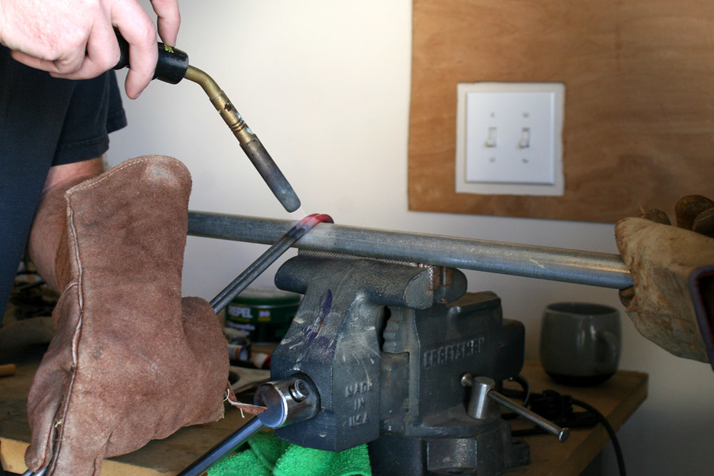
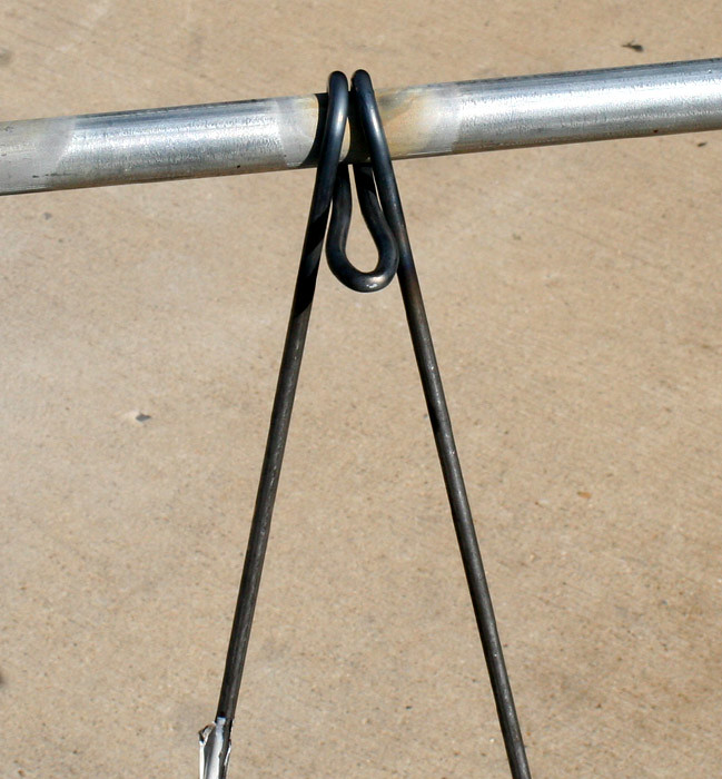
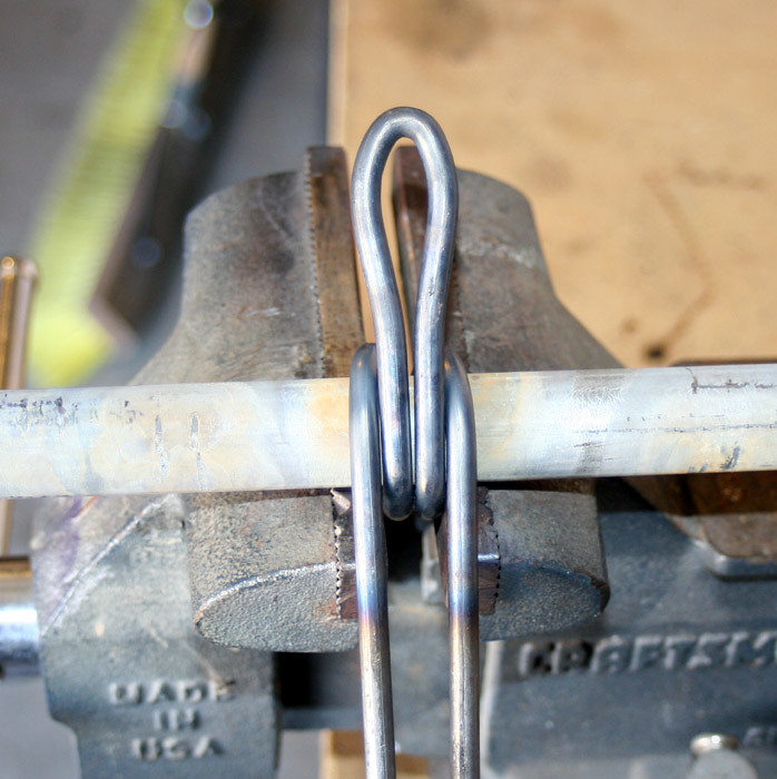
I got out a length of 3/4" tubing, clamped the U-shaped end of the mount into the vise, and started bending the rod around the tubing. Since I needed to start the bend at the marks I had made earlier, I placed those marks
just above center line of the 3/4 tubing. Heat, patience, and more heat...just follow slightly ahead of your bend with the torch and pull ever so slightly on the rod as you bend.
I kept going and bent as far as I could without rotating the part in the vise. Notice the rails are splayed out here. Not a big deal. That will get taken care of as I continue.
Repositioned the piece in the vise and kept bending. A full 360 degree bend at this point
Went around another 180 degrees. Made sure to spread the rails apart a bit as I finished coiling the rod. Remember, the seat post and mounting hardware has to fit between the rails.
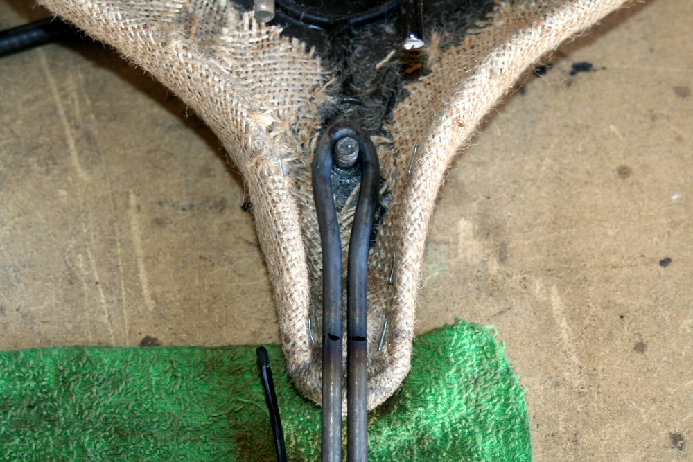
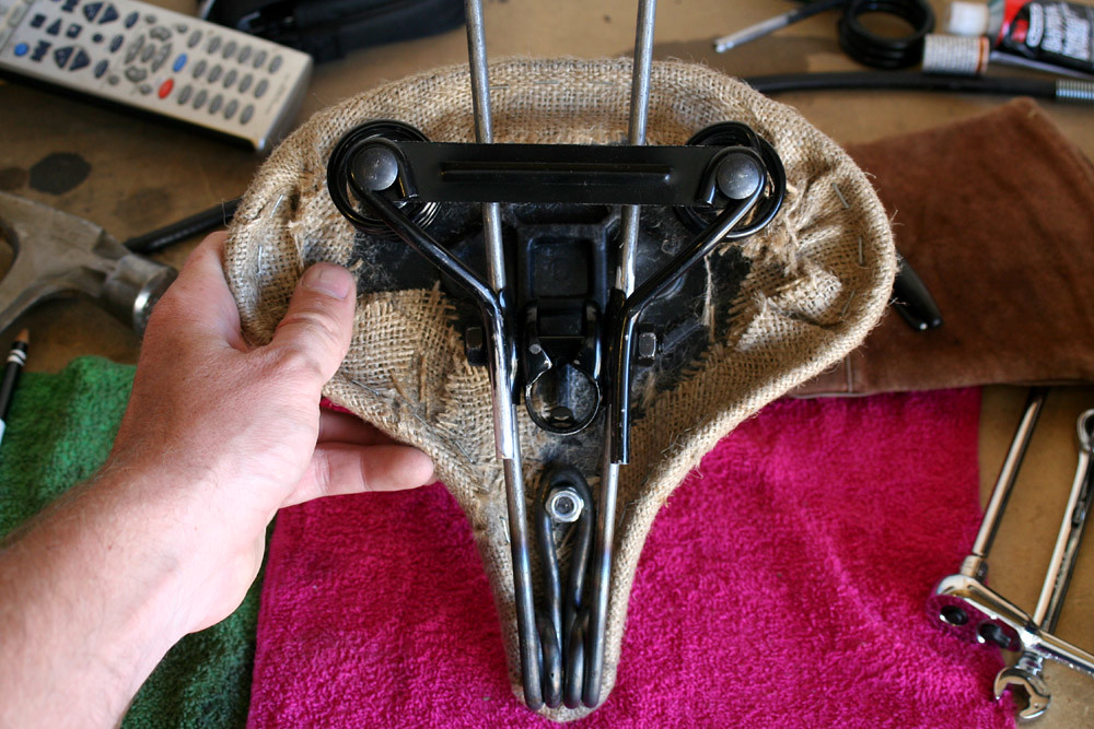
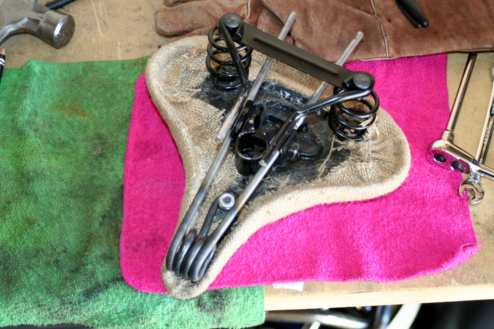
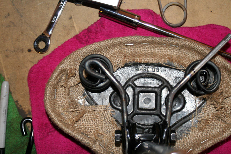
Allowed the part to cool and mounted it to the seat pan and assembled the seat post and mount to gauge what to do next.
Everything was looking good. I used a Sharpie to mark bend points to bend the new rails towards the coil springs like the stock mounting rails.
Having the old rails in place really helped judge where the next bends would need to be. I heated the rails and bent them so that they followed the same path of the stock Huffy rails to the rear springs.
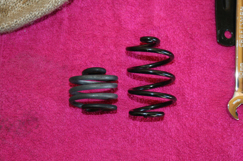
To make things work like I felt they should (and look like I felt it should) I decided to give the stock Huffy springs some attention. They're normally 2 1/2" tall. I measured the location of my seat rails and found them to be right at half - 1 1/4". I placed each spring in the vise, closed the jaws to 1 1/4", and heated the springs. Doing this can be tricky because hey - springs store energy. If you focus the heat on one section of the spring for too long the spring will deform. You'll see the coils move. Gradually heat the entire spring and pay attention to how the coils move as you apply heat. You can actually manipulate spacing between the coils by moving the heat source.
When you're happy the coil should just drop out of the vise jaws without loosening the jaws.
Before and after.
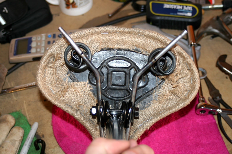
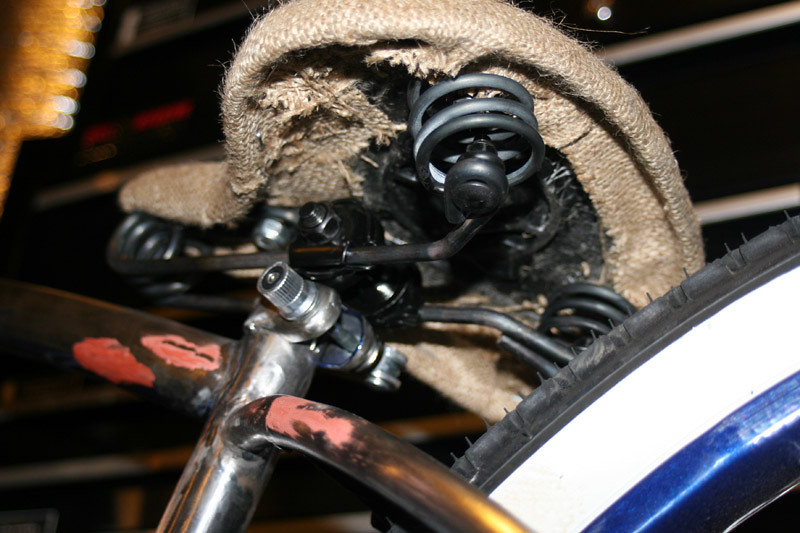
I mounted the modified springs to the seat pan so I could find my next bend points.
Sharpie was used again to mark the starting point for the final bend. Just a 270 or so degree bend to allow the mounting rails to be bolted to the coils.
Used a section from the stock seat rails to wrap the rod around. Before and after for this final bend pictured here.
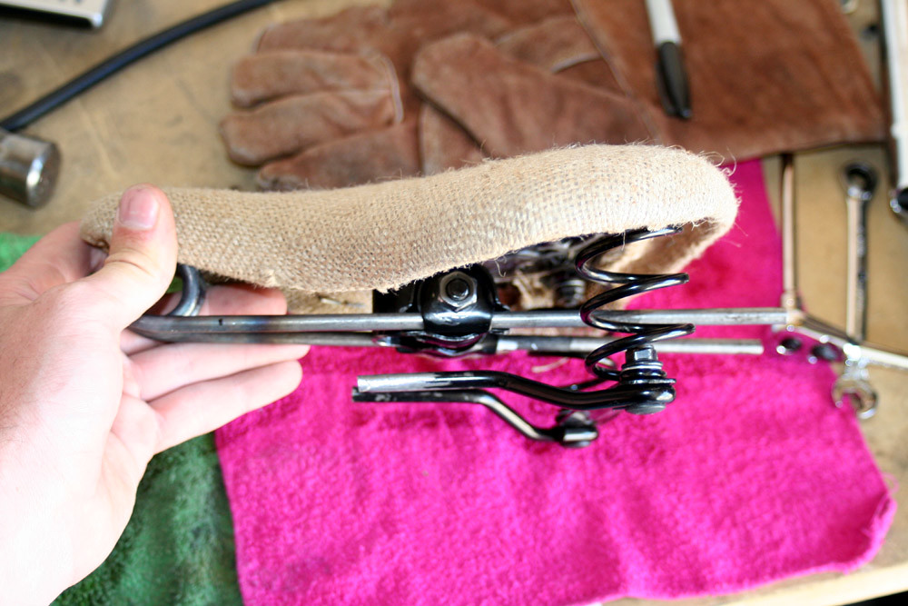
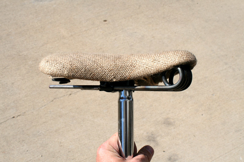
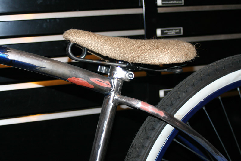
With the new unit completed it was time to fit it to the bike and see how it looked. The new rails have more fore/aft movement than the stock Huffy rails could've dreamed of. Megan likes it.
Tomorrow I'll slot the seat tube to get better clamping action from the seatpost clamp and trim the excess burlap from the underside of the seat (...or saddle :lol
")
Anyway...that part is done. :mrgreen:
For what it's worth, it took exactly 36 inches of steel rod to make this. :lol: