


I've been on this forum for around a month and i've asked a lot of questions, now it's time to answer one, how do i make a custom led light from a truck marker light? Well, glad you asked!
Supplies you will need: marker light (i got mine from Mike at VBS in Sacramento just like this one only red http://www.12volt-travel.com/25-beehive ... -5238.html ), round printed curcuit board (pcb), wire (16-22 gauge), 3 leds (red, 10mm, 2.4 V, 20 mA), resistor (10 ohm 1/4 watt), toggle switch, bullet or spade connectors for 16-22 gauge wire, 2 x AAA battery holder and batteries, solder (.032" diameter), super glue.
Tools: Soldering iron, wire stripper/cutter, drill, flat tip screwdriver or similar device (for removal of the lock ring on the lens), cone shaped metal file or rotary tool with grinding wheel for cleaning up holes (optional but highly recommended), angle grinder (optional, for removing excess bracket length). Most of your supplies maybe found at Radio Shack however i recommend OSH or a hardware store first for wire and solder and connectors as they are cheaper. Also, please read all instructions before starting.
First this is the printed circuit board:
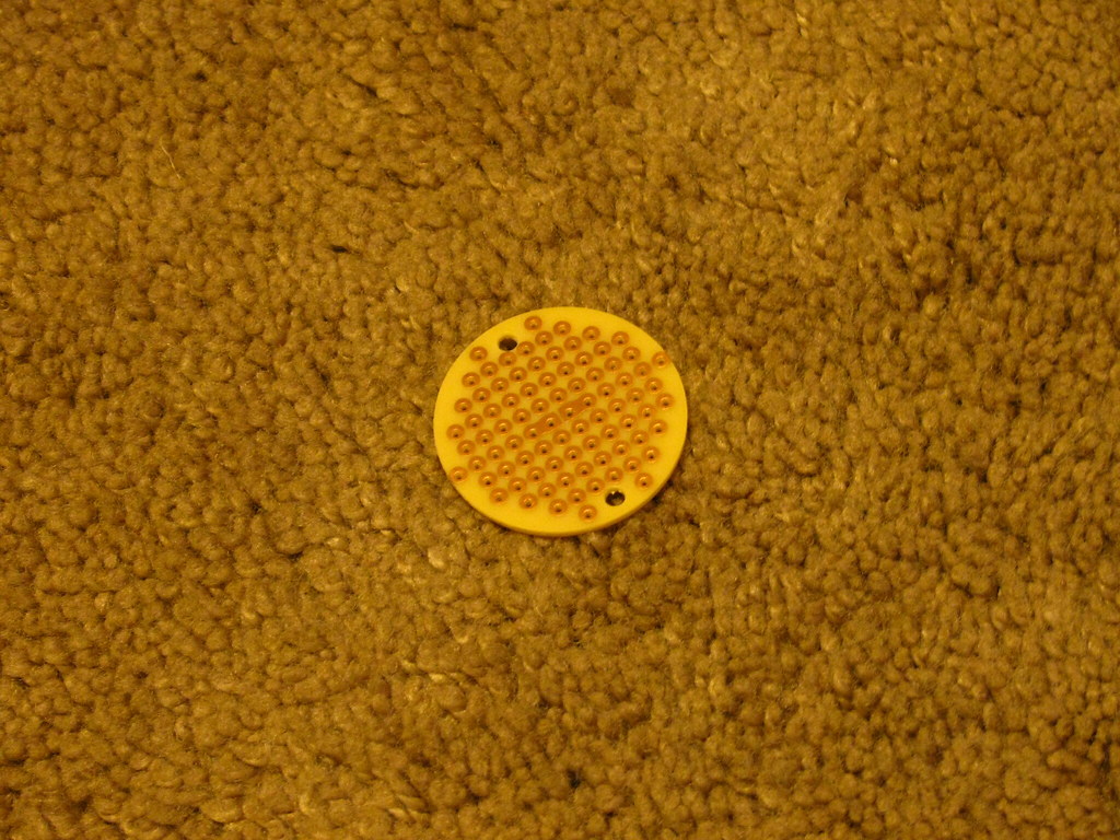
The led goes in from the side without copper on it, this is a sample picture with just one led
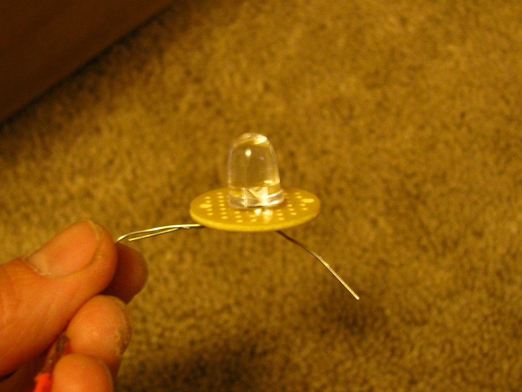
Place the leds in a triangle pattern as shown below with the led leads facing just as they are in the photo below, make sure they are sitting flush before bending the leads.
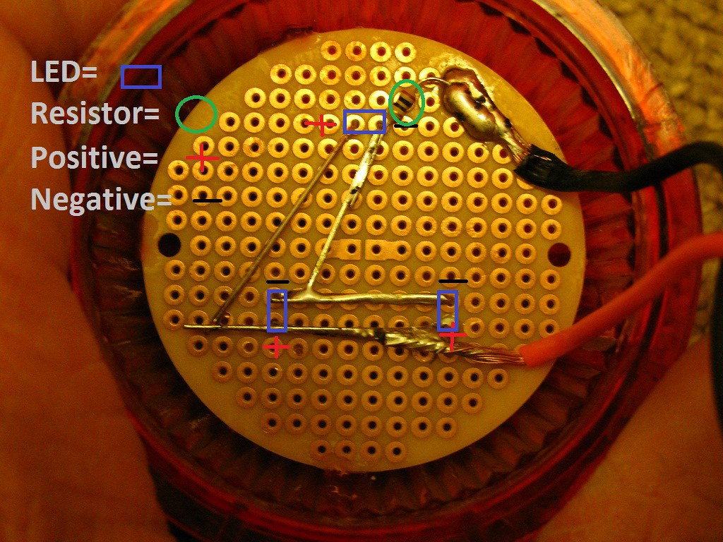
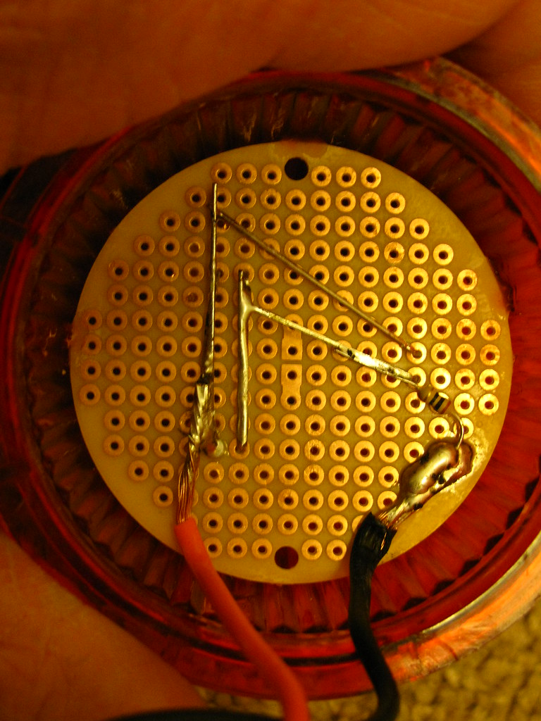
Bend the leads down so that all the negative leads are touching each other and the positives are touching all the other positives (look at the picture to see which direction to bend). You will have to trim the negative leads on the inside so they do not contact the positive leads. connect with a bit of solder and repeat for the positive leads. Next solder your resistor to the negative side leads then solder to the wire and pcb. Here is a picture without the diagram for clarification.
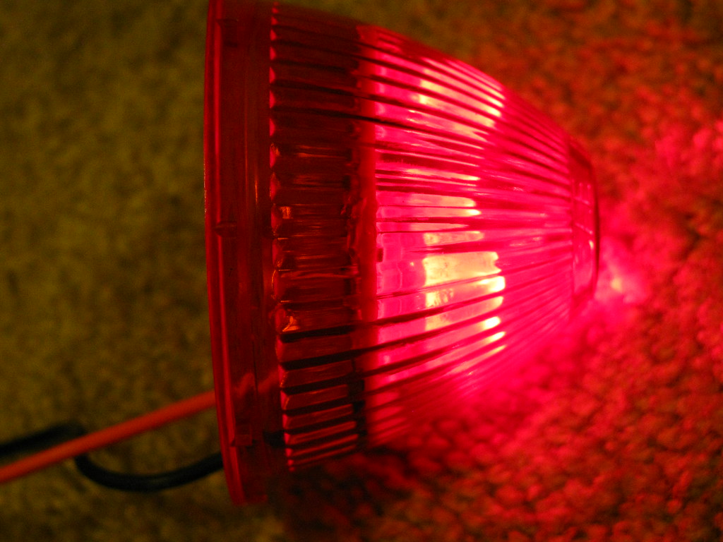
Solder your positive wire on to the leads and pcb. For your positive wire you need only a few inches so that you can reach the switch and leave enough room to remove the lense. Take the finished pcb and use 3 or 4 drops to glue to the inside of the lense, make sure it's level! I've turned the light on to show about how far down i put mine.
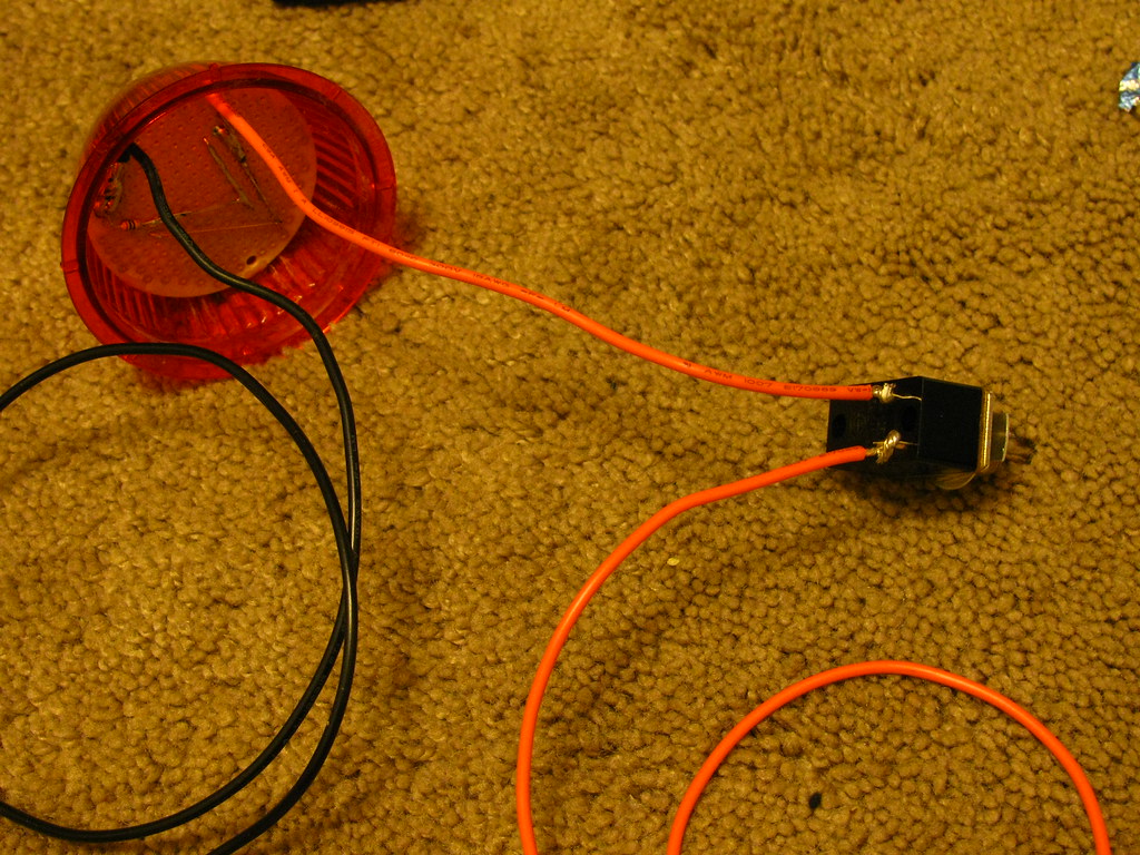
Next solder the positive wire from the pcb to one terminal on the switch and another piece of wire to the other side, be sure to give your wires enough length to run your battery pack where you will install it. Mine is going to be under the rear fender which will also allow me to hide most of the wiring along the fender support brace.
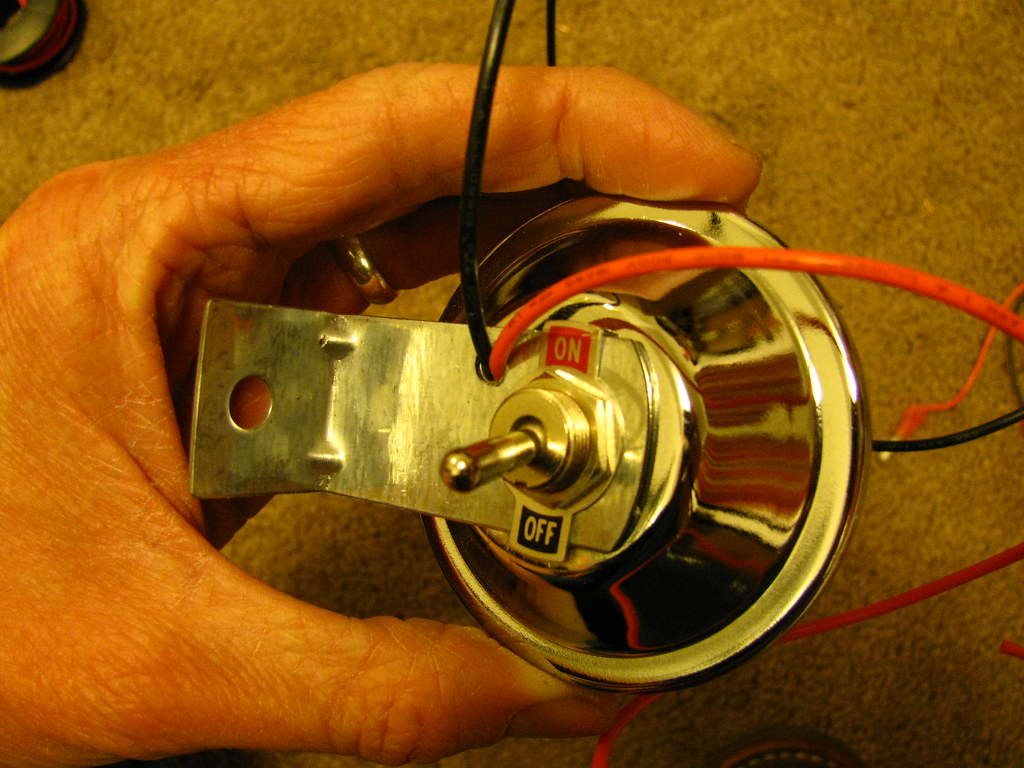
Next you will most likely need to drill or file out the original hole used for the incandescent bulb (the whole incandescent bulb assembly should be removed now if it has not been, including the grommet used to hold on the bracket for the light, don't worry the switch will hold this together if you have a toggle switch the same as the one pictured with an on/off washer). I used a 1/2 bit with little success, the metal is very thin and the bit tends to bind up and tear the metal, if you have a file use that instead. Repeat this for the bracket so your switch goes through both. Once you have the switch properly installed and the bracket at the correct angle drill a second hole through the back of the light and bracket large enough for both wires to exit (i used and 11/64 for 18 gauge wires).
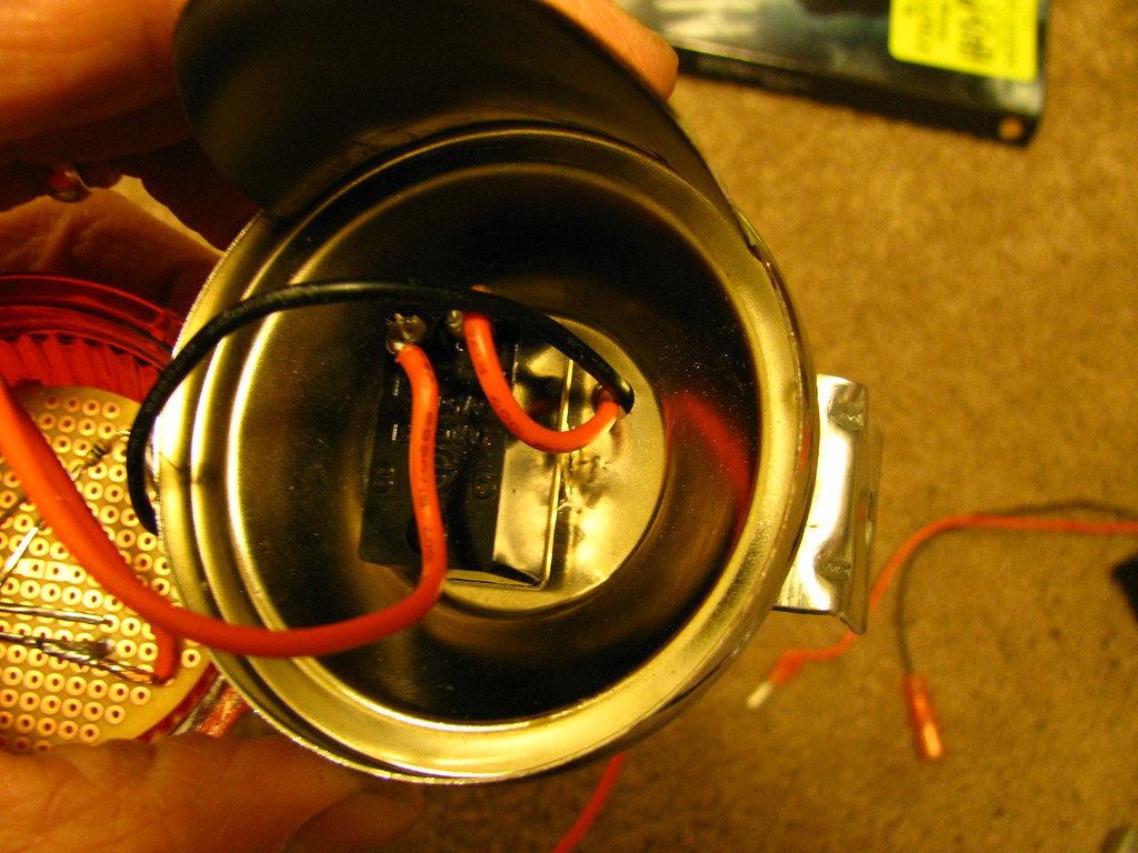
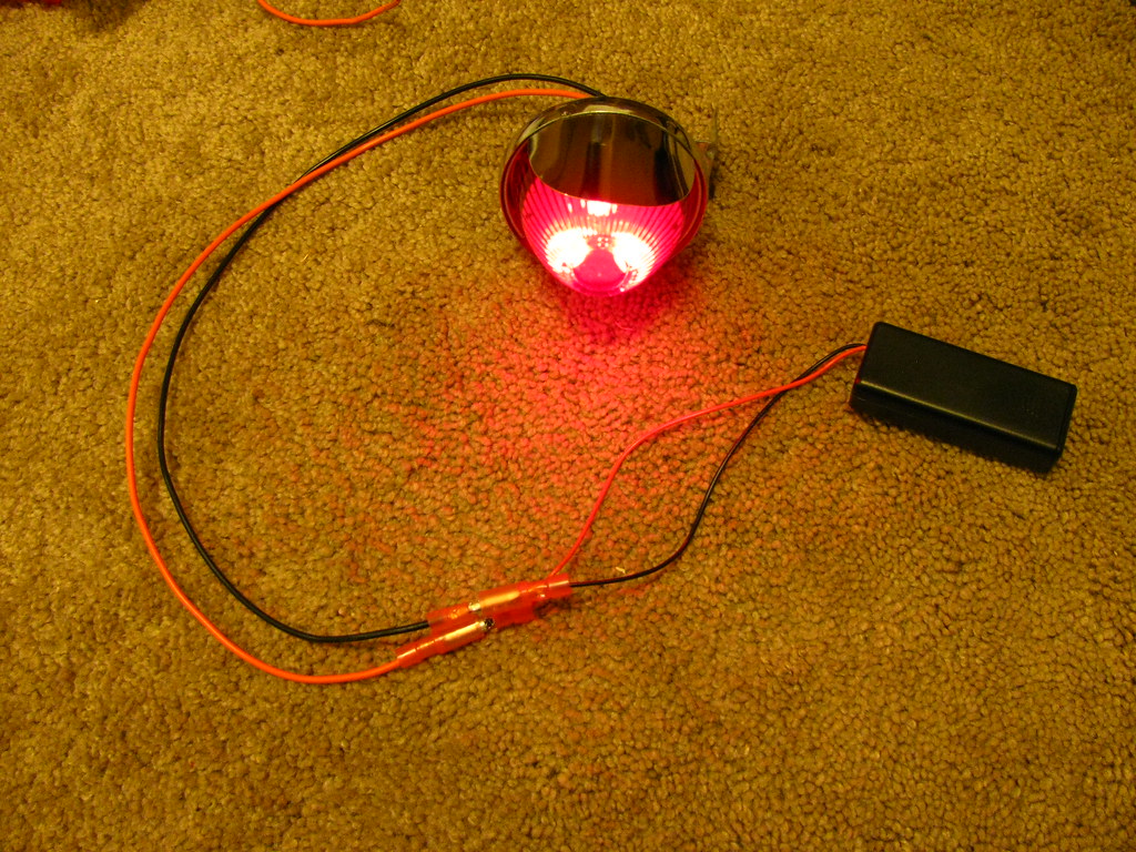
I know this appears to be a finished product photo but you have one more step, attach the bullet connectors so you can attach your battery holder. You may need to fold the stripped section of the battery holder wires to work in the connectors as they are quite thin.
You of course must now install on your bike but you have one tidy looking rear light with retro appeal and modern functionality. I'm putting my batteries under the fender, you may try under the seat or you could not hide them at all if you wish but i think that defeats the purpose of this set up. I also trimed the bracket on the side not attached to the light, it had two holes for easier install but i need just one so i used the angle grinder and cleaned it up with the dremel. Good luck and PM me if you need help.
Some side notes, you don't have to use pcb it is just very easy and clean, wood or plastic would work and please use the leds and resistor and batteries i have listed here unless you know electronics math. Altering any one of those factors may fry your whole system. Big thanks to my brother who is an electronics student and humored me by doing some very basic electronics algebra and provided hands 1 and 2 for soldering, i had 3 and 4 (hint: having 4 hands for the soldering is very helpful!). Hopefully this will make it to the how too manual thread!
Supplies you will need: marker light (i got mine from Mike at VBS in Sacramento just like this one only red http://www.12volt-travel.com/25-beehive ... -5238.html ), round printed curcuit board (pcb), wire (16-22 gauge), 3 leds (red, 10mm, 2.4 V, 20 mA), resistor (10 ohm 1/4 watt), toggle switch, bullet or spade connectors for 16-22 gauge wire, 2 x AAA battery holder and batteries, solder (.032" diameter), super glue.
Tools: Soldering iron, wire stripper/cutter, drill, flat tip screwdriver or similar device (for removal of the lock ring on the lens), cone shaped metal file or rotary tool with grinding wheel for cleaning up holes (optional but highly recommended), angle grinder (optional, for removing excess bracket length). Most of your supplies maybe found at Radio Shack however i recommend OSH or a hardware store first for wire and solder and connectors as they are cheaper. Also, please read all instructions before starting.
First this is the printed circuit board:
The led goes in from the side without copper on it, this is a sample picture with just one led
Place the leds in a triangle pattern as shown below with the led leads facing just as they are in the photo below, make sure they are sitting flush before bending the leads.
Bend the leads down so that all the negative leads are touching each other and the positives are touching all the other positives (look at the picture to see which direction to bend). You will have to trim the negative leads on the inside so they do not contact the positive leads. connect with a bit of solder and repeat for the positive leads. Next solder your resistor to the negative side leads then solder to the wire and pcb. Here is a picture without the diagram for clarification.
Solder your positive wire on to the leads and pcb. For your positive wire you need only a few inches so that you can reach the switch and leave enough room to remove the lense. Take the finished pcb and use 3 or 4 drops to glue to the inside of the lense, make sure it's level! I've turned the light on to show about how far down i put mine.
Next solder the positive wire from the pcb to one terminal on the switch and another piece of wire to the other side, be sure to give your wires enough length to run your battery pack where you will install it. Mine is going to be under the rear fender which will also allow me to hide most of the wiring along the fender support brace.
Next you will most likely need to drill or file out the original hole used for the incandescent bulb (the whole incandescent bulb assembly should be removed now if it has not been, including the grommet used to hold on the bracket for the light, don't worry the switch will hold this together if you have a toggle switch the same as the one pictured with an on/off washer). I used a 1/2 bit with little success, the metal is very thin and the bit tends to bind up and tear the metal, if you have a file use that instead. Repeat this for the bracket so your switch goes through both. Once you have the switch properly installed and the bracket at the correct angle drill a second hole through the back of the light and bracket large enough for both wires to exit (i used and 11/64 for 18 gauge wires).
I know this appears to be a finished product photo but you have one more step, attach the bullet connectors so you can attach your battery holder. You may need to fold the stripped section of the battery holder wires to work in the connectors as they are quite thin.
You of course must now install on your bike but you have one tidy looking rear light with retro appeal and modern functionality. I'm putting my batteries under the fender, you may try under the seat or you could not hide them at all if you wish but i think that defeats the purpose of this set up. I also trimed the bracket on the side not attached to the light, it had two holes for easier install but i need just one so i used the angle grinder and cleaned it up with the dremel. Good luck and PM me if you need help.
Some side notes, you don't have to use pcb it is just very easy and clean, wood or plastic would work and please use the leds and resistor and batteries i have listed here unless you know electronics math. Altering any one of those factors may fry your whole system. Big thanks to my brother who is an electronics student and humored me by doing some very basic electronics algebra and provided hands 1 and 2 for soldering, i had 3 and 4 (hint: having 4 hands for the soldering is very helpful!). Hopefully this will make it to the how too manual thread!