Fork #2

Rat Rod Bikes Bicycle Forum

Help Support Rat Rod Bikes Bicycle Forum:

This site may earn a commission from merchant affiliate links, including eBay, Amazon, and others.
Joined
Aug 14, 2013
Messages
612
Reaction score
483
Location
Ca
Rating - 0%
0   0   0
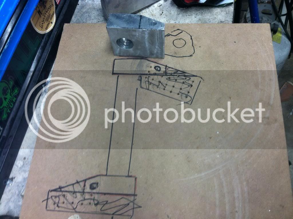
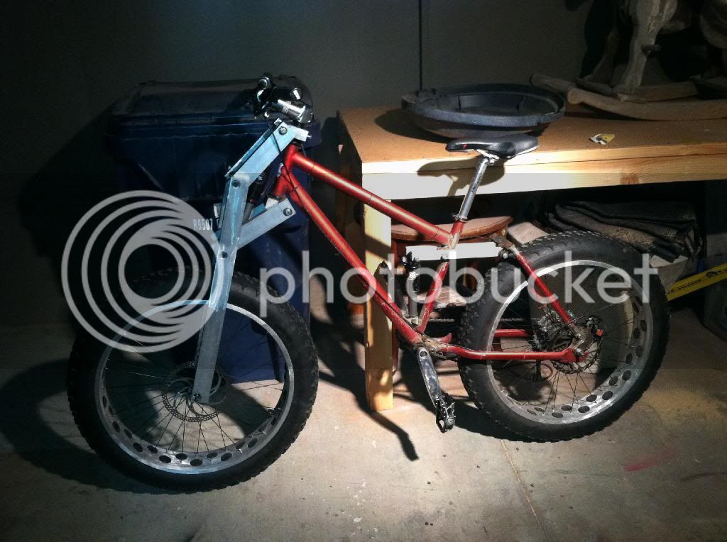
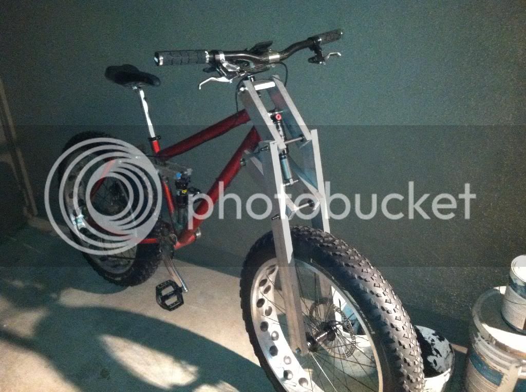
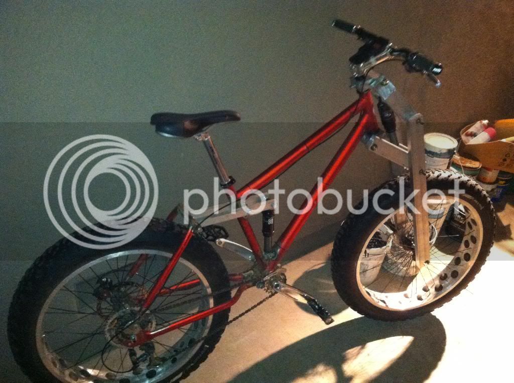
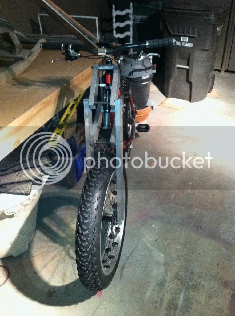
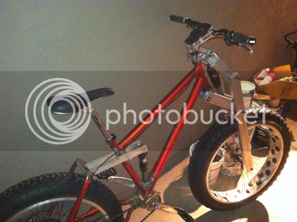
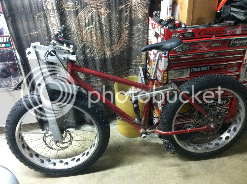
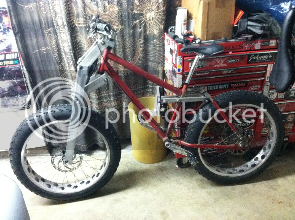
I am starting another fork for my Beast. This one is going to be way different from the first. First off its going to be make with a lot more aluminum, plus its going to have a lot more travel, and I am using a way better shock. I need to find a place to get bearings that won't break the bank.

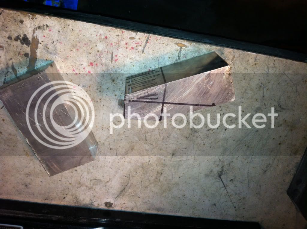
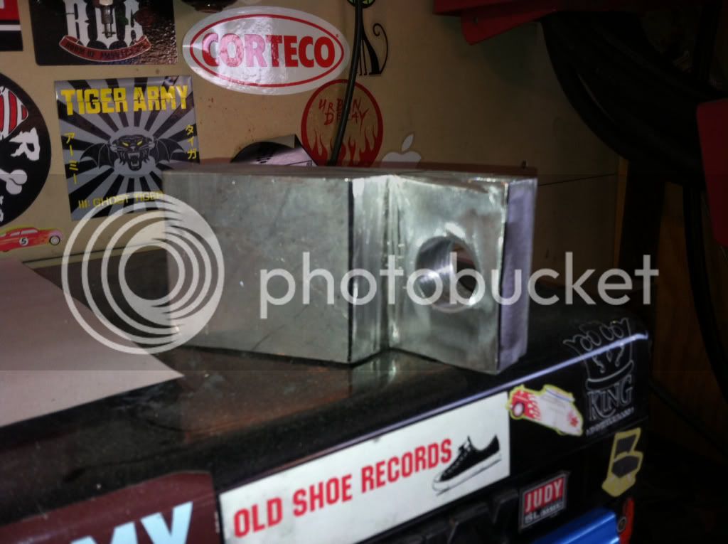
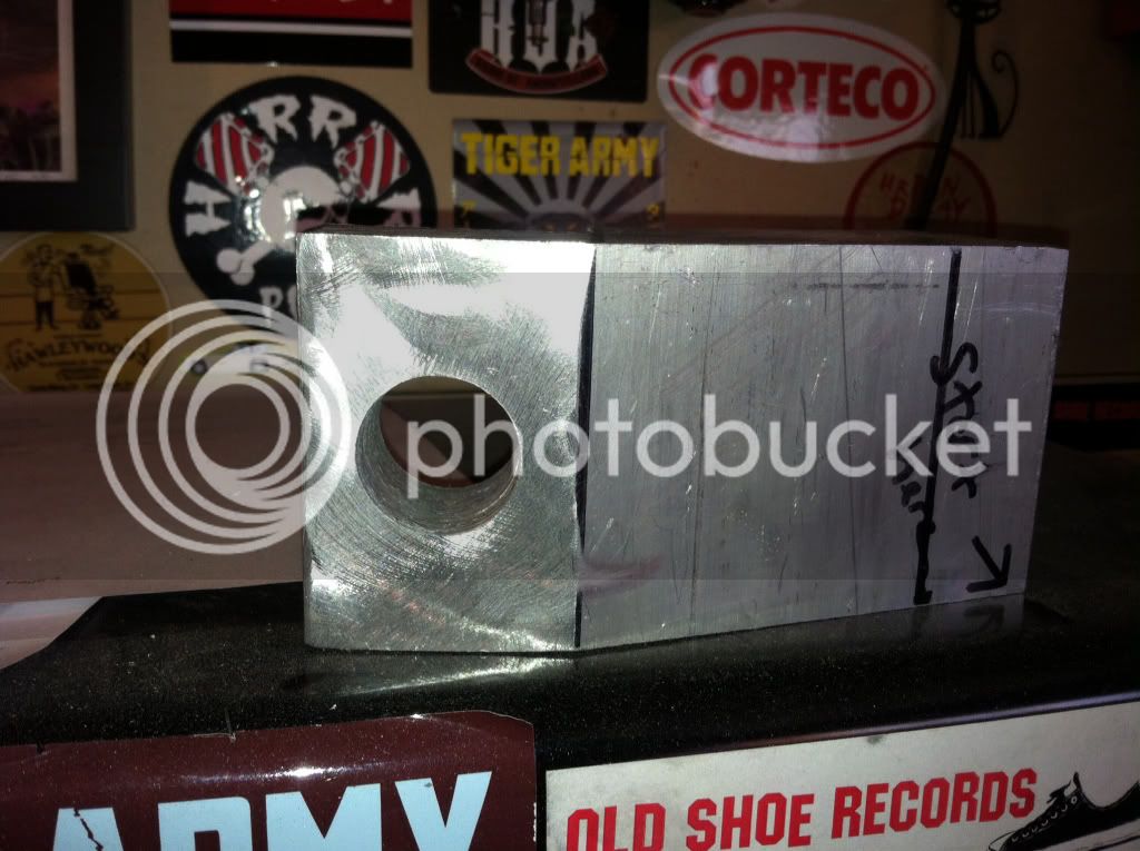
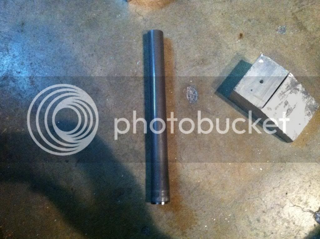
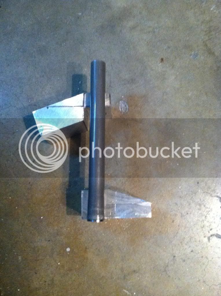
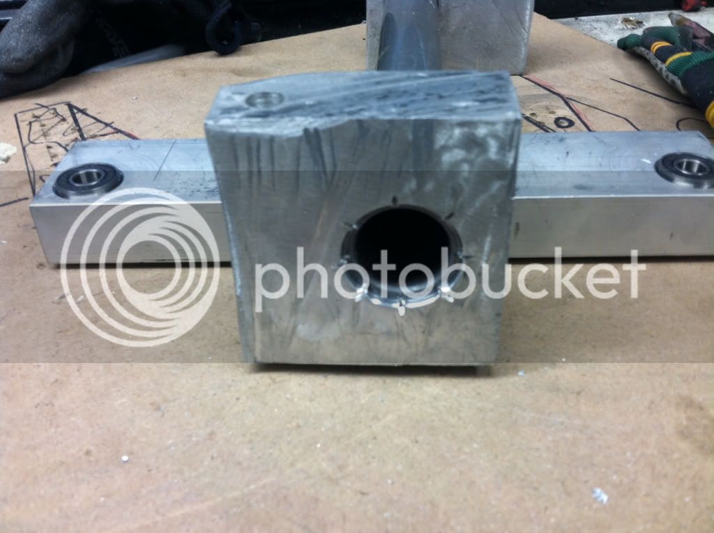
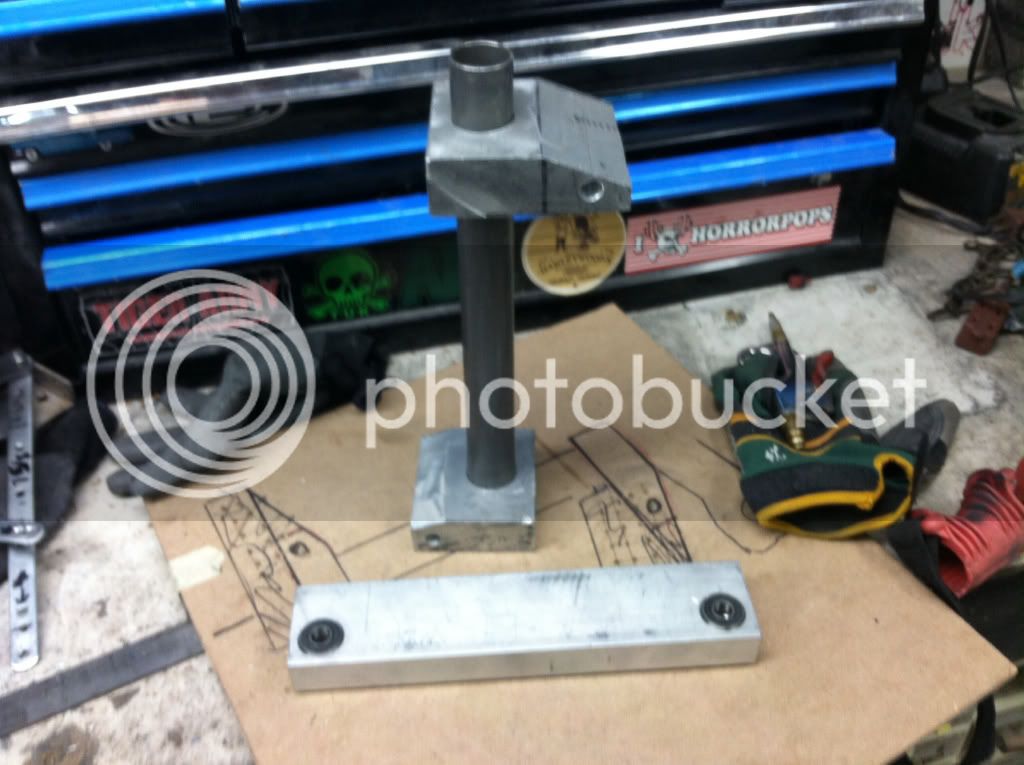
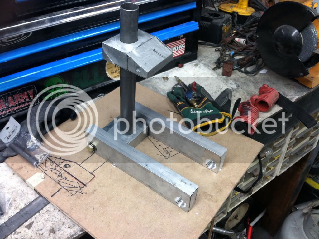
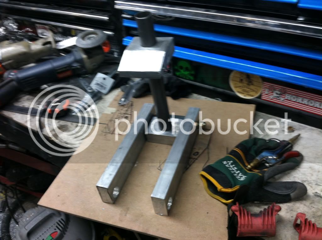
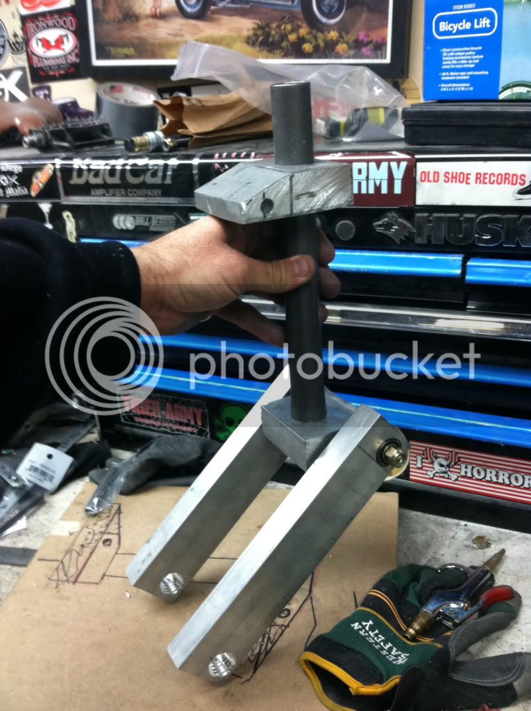
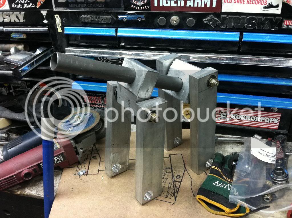
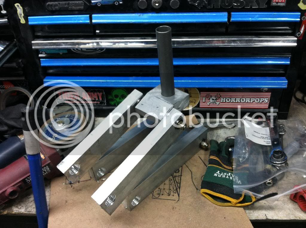
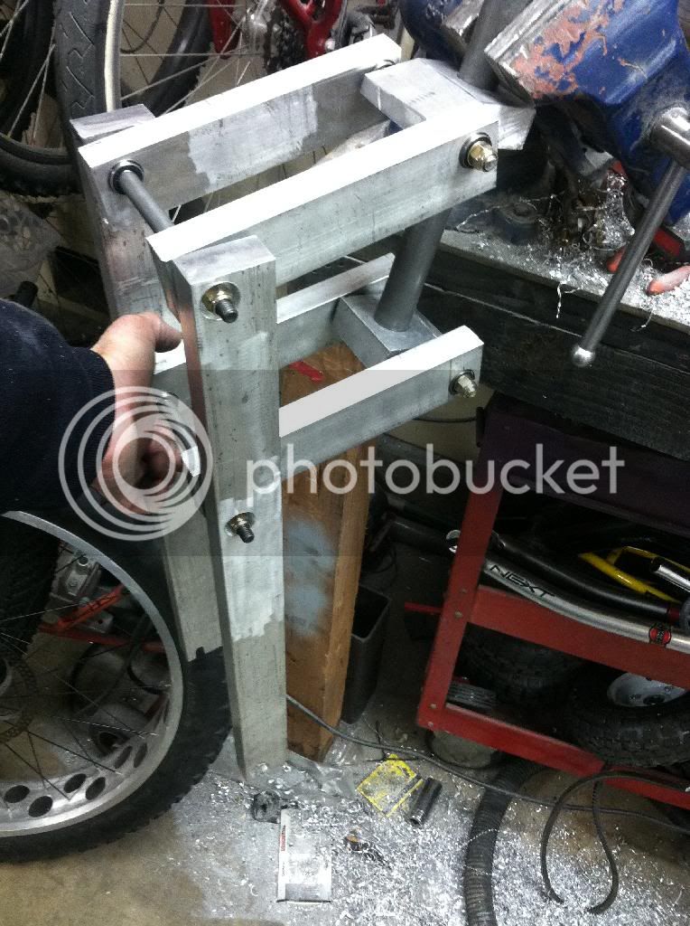
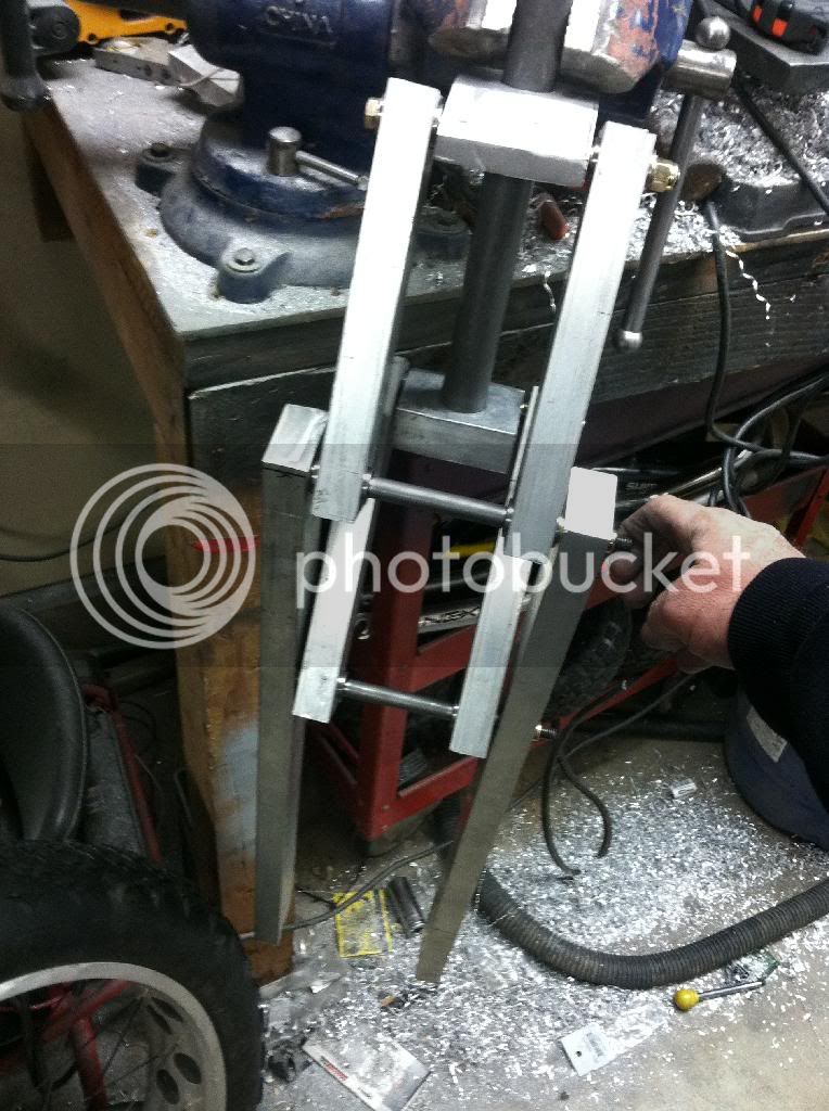
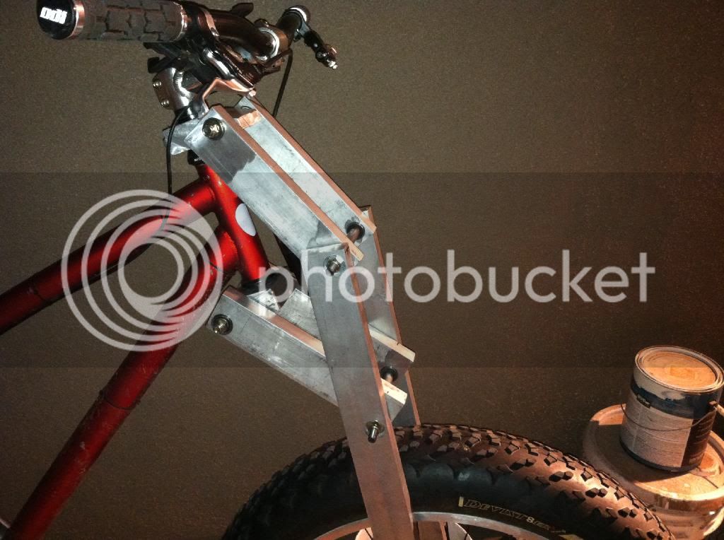
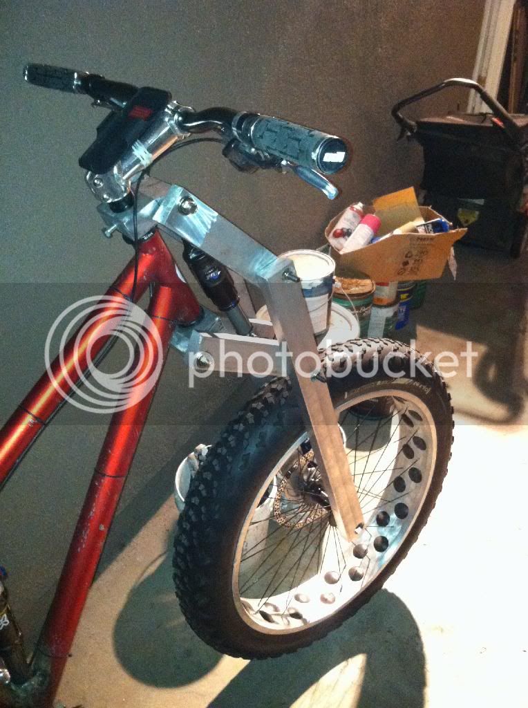
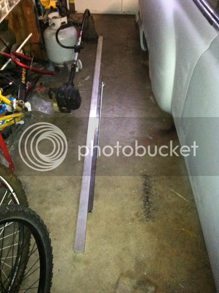
Yesterday i got the aluminum. 6061t6 to be exact. The legs and links will be made from 1"x2" solid bar. Once the basic shape is done, ill mill out all the excess material to make them lighter. I got 8 feet of this stuff!

image_zps38255dea.jpg


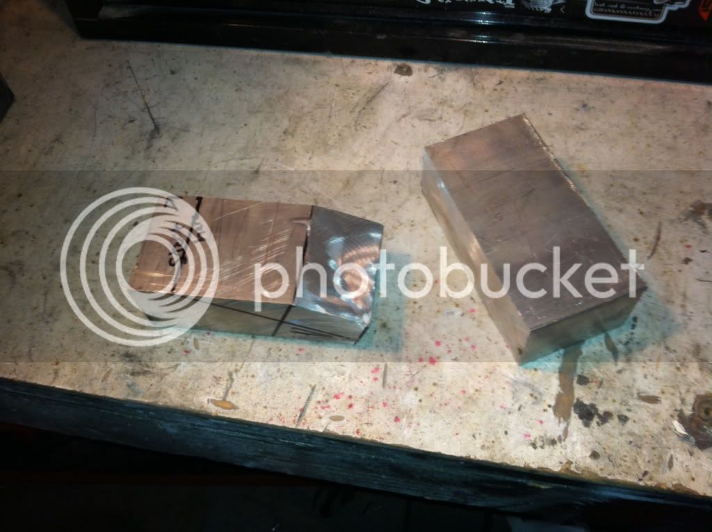
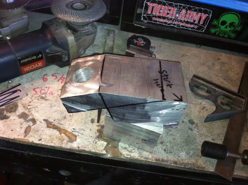
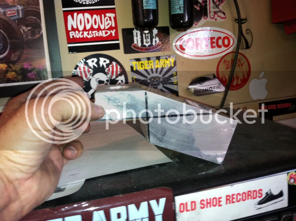
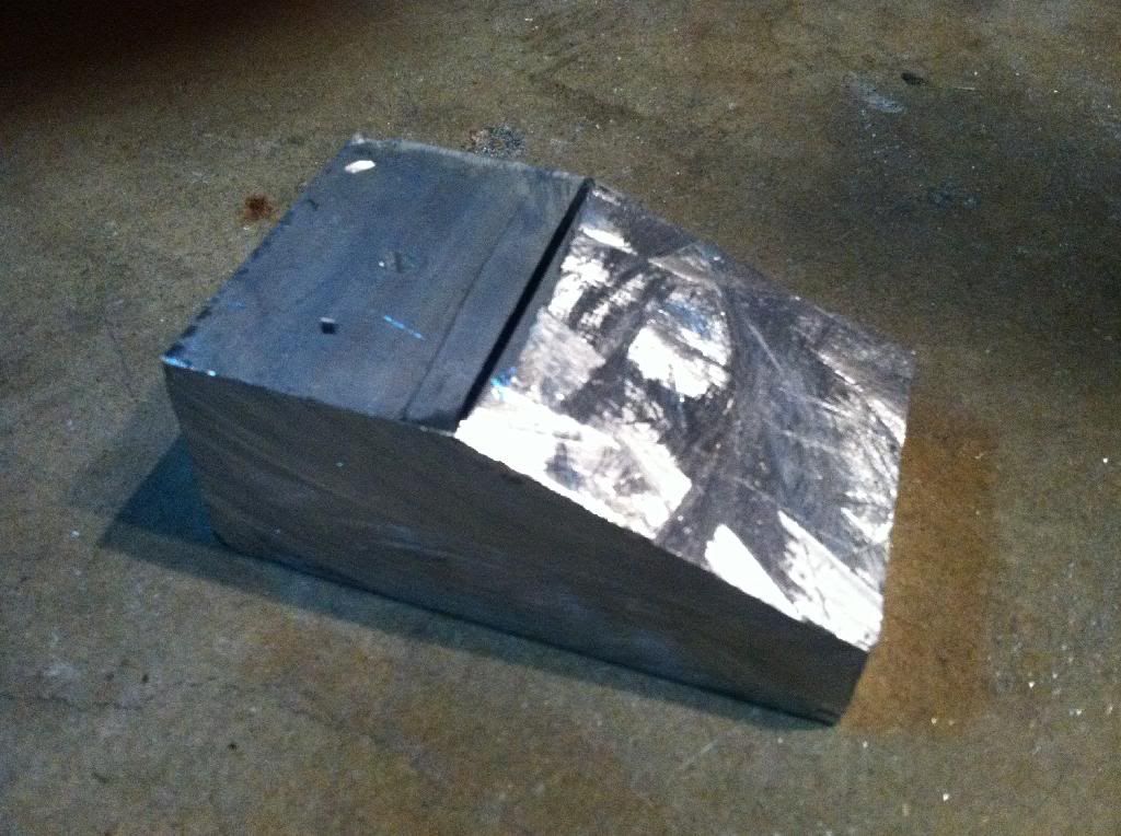
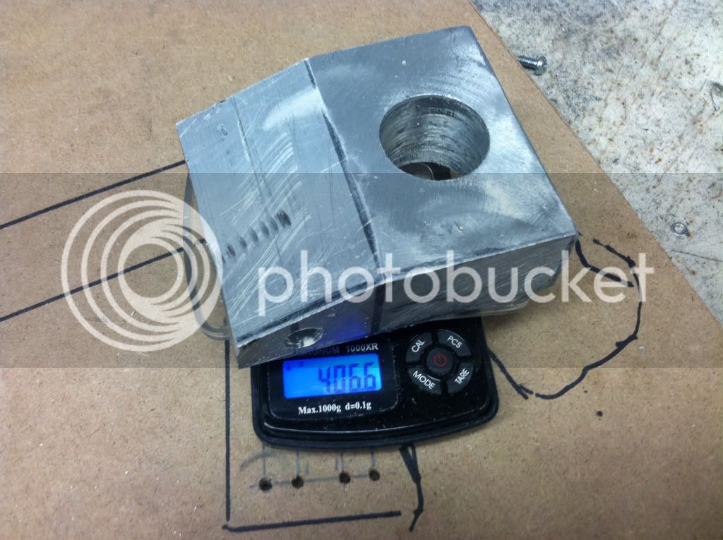
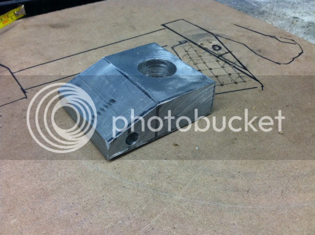
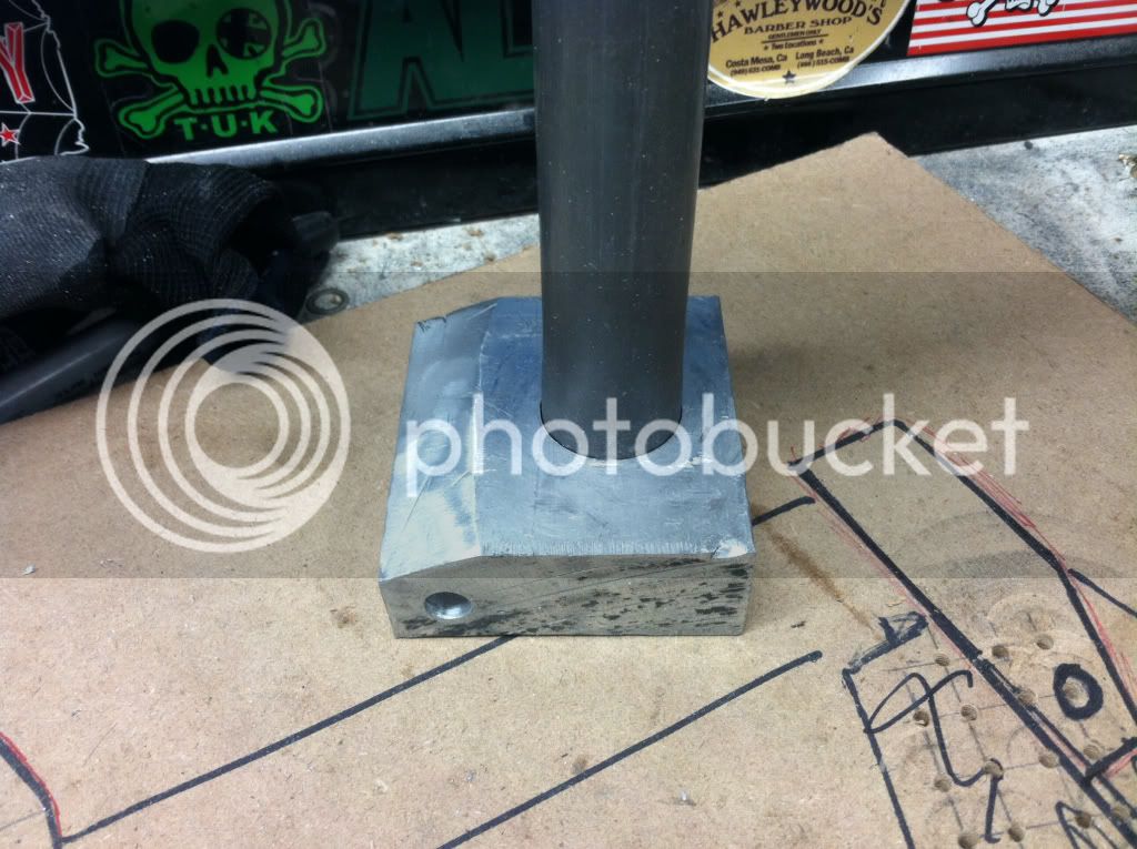
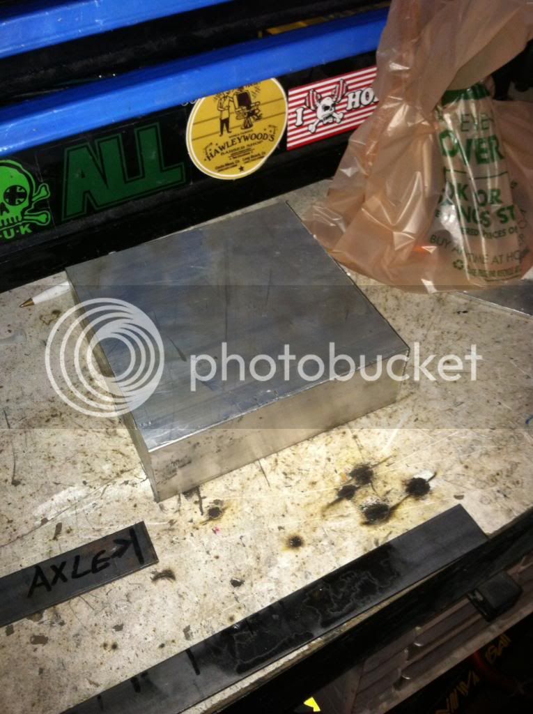
Then I found a chunk of 6061t6 that is 6"x6"x2". this will become the upper and lower crowns. Ive got some cool ideas for offset crowns!

image_zps81ebccca.jpg


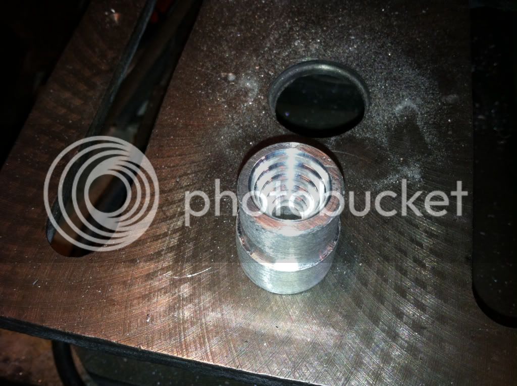
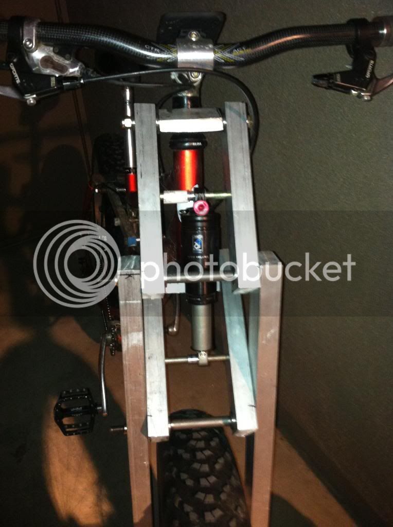
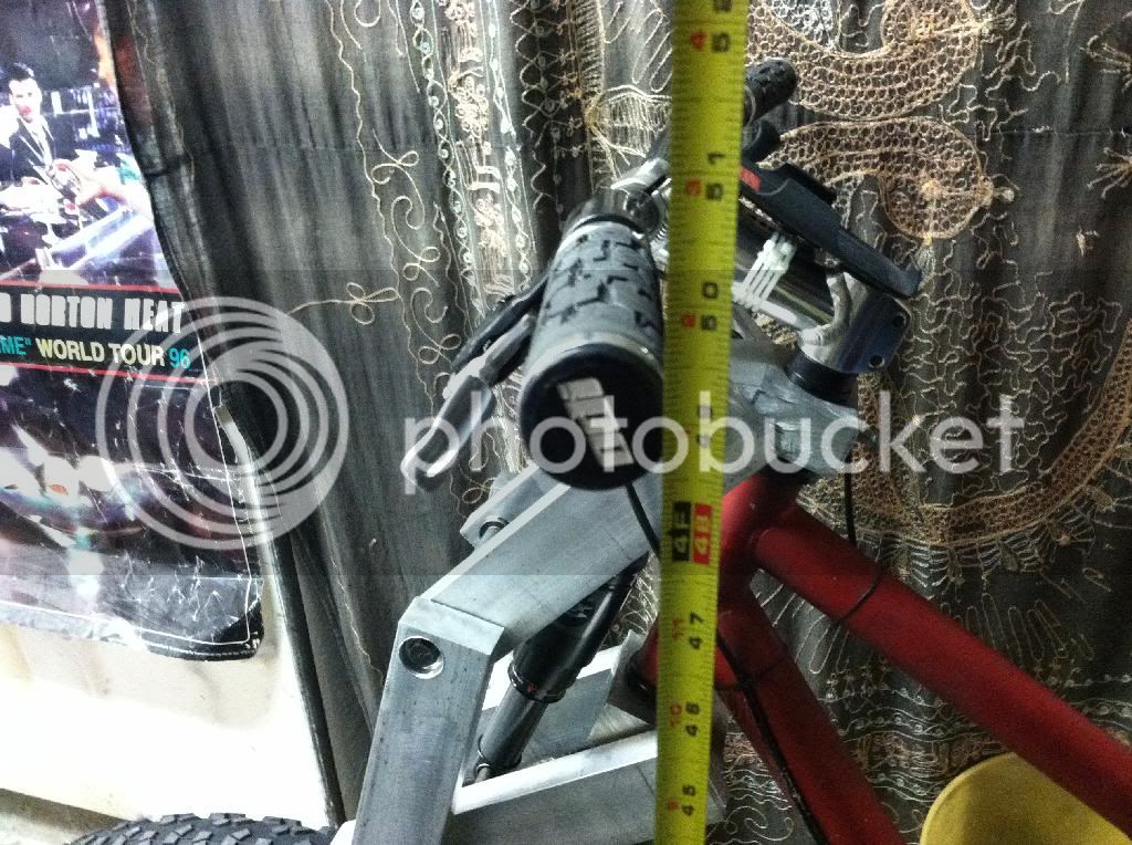
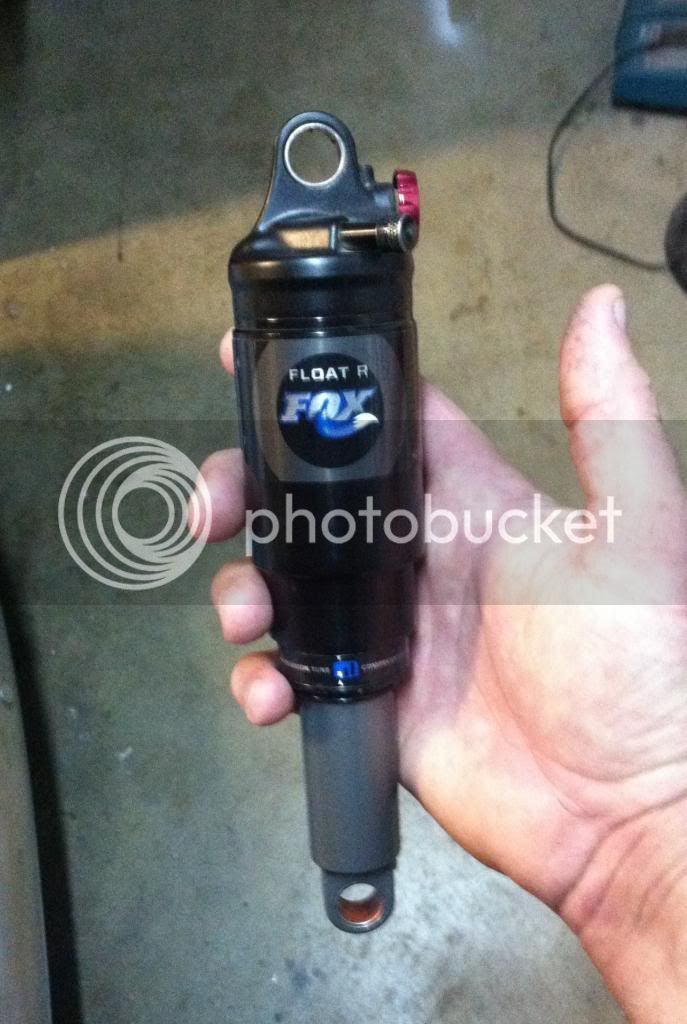
Here is the shock. Its a Fox Float R with adjustable compression and pro pedal. Its 8 1/2 inches long with 2 1/2 inches of stroke. I got it a couple weeks ago, used for a real good price:

778492c5-8c96-4cb7-a432-3aacb625a165_zps0368e17c.jpg


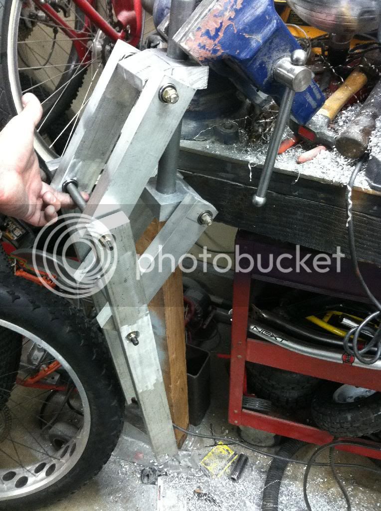
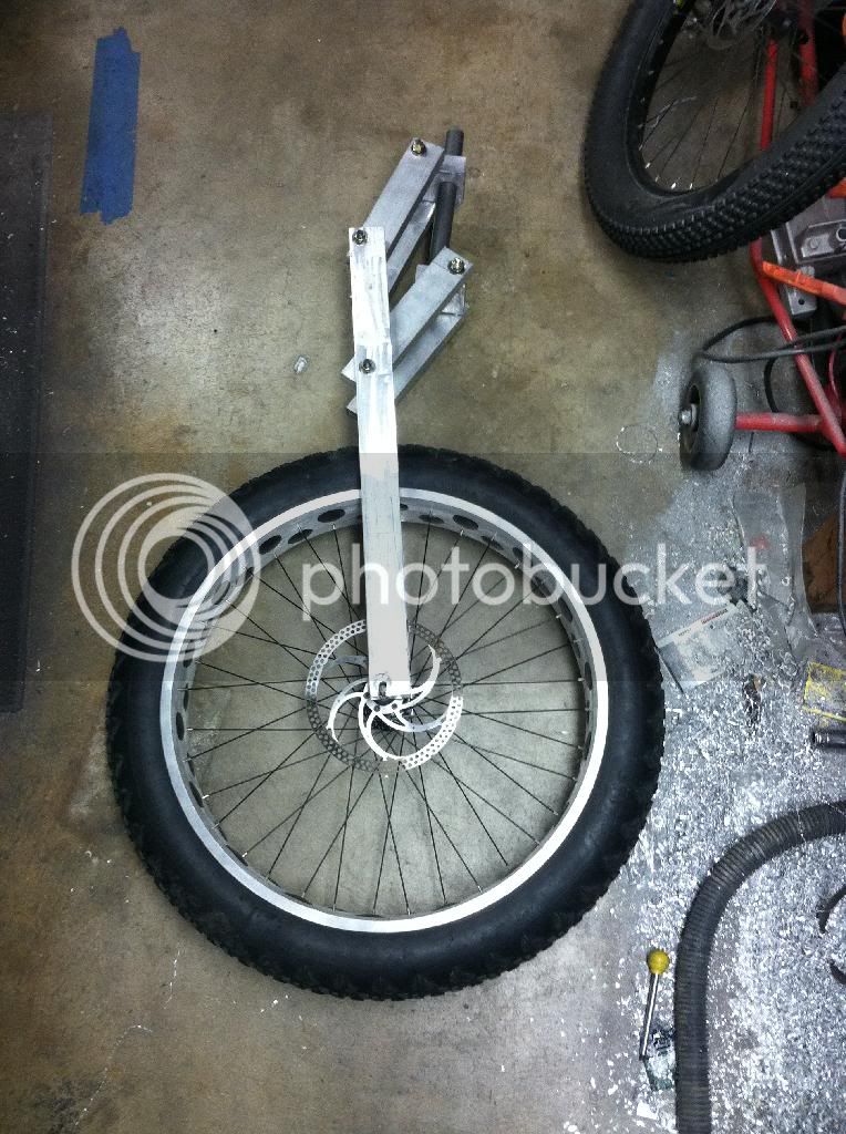
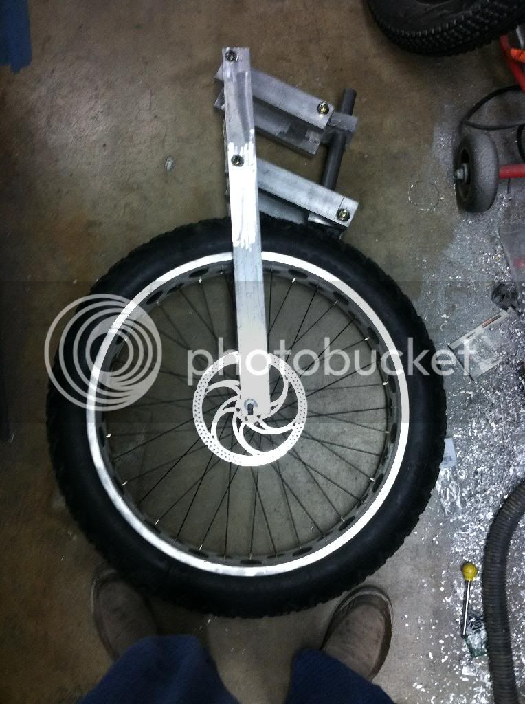
I have learned a ton about linkage forks since the first one I made, this fork should be WAAAAAAY better than the last, as long as I don't screw it up while making it! I am hoping for 6 1/2 to 8 inches of travel. The links will be different lengths, so that I can play with the axle path more. Hopefully the axle path will be slightly curved, with the initial travel pulling the wheel back so that I don't get brake dive. Also the crowns will be offset from the steerer tube so that the trail and rake of the fork will be better. Its going to take me a lot longer to make this one than the last because of all the milling ill have to do, but the results will be worth it!
 
I started to work on the crowns last night, or at least I tried too.

I was using my Harbor Freight miter saw as a chop saw. I had a vacuum hooked up to the dust collector, so I didn't notice when the motor started smoking. 12 minutes into cutting the big block of aluminum in half and it started to give me a lightning show from the motor. I pulled it apart to see if it was something obvious and didn't see anything. Must be burn windings... Oh well, it lasted 12 years. My grinder ended up going out last night too, but it was late, so I haven't had a chance to see if its fixable yet.

1182b3f09d87f34b83418941438be7ff_zpsd33c6a1c.jpg


I used a grinder and a hand saw to finish cutting the block in half and to start roughing in the shape of the upper crown. I need to see how the crowns end up before I can finalize the linkage geometry.

37c0058423e66bc2835348494dcc520c_zps76a355ec.jpg


e306142684629c26027acb2ff552bd50_zpsecefef87.jpg
 
I got the upper crown roughed in today. Its far enough along for me to use it to get the final geometry set. At its thinnest point, its 1" thick. I need to do the lower crown next.

f74e5c292fdd8409771688eb9170b862_zps8d78616d.jpg


884c22add72754501f944d8b2a3e9770_zps61ed6d96.jpg


a69b7476f629a57e0b4d6c00cd0e2ce2_zpsa117d10e.jpg


d85c5f98b9cc75ca90d2e8317a3853b0_zps18270fa2.jpg


One thing I really like about working with aluminum; Even the trash looks cool!

602642235b7a52a74c5dfcefff0dc4b7_zpsfe3e137a.jpg


361a03252f460fa13243fd6da87684e1_zps98198e0d.jpg
 
Small update:

I got a steerer tube off of Amazon.com. I was about $15 and is plenty long. Also I got the lower crown roughed in. Next step is to drill the lower crown for the steer tube and finalize the geometry and travel of the fork. I will probably end up making these crowns a lot smaller, but at this size I have lots of options.

Work on this fork will be slow. My wife is 9 months pregnant with kid #3, so my garage time is less than it used to be.

21A22A4D-B78D-49A9-9FD2-06CC5B758DAC_zpsrlae3yhy.jpg


E9118B3E-BC68-473C-B6C6-54A9B37D8B75_zpsoqz5lrdn.jpg


E6CE2D13-2A71-4D44-907C-8D2340D1313A_zpsrqn6gjjf.jpg
 
Last night I got the geometry of the linkage worked out. Its going to be pretty rad!

The trail will be about 55mm at full extension, then it curves back to 50mm at about 3 inches compression. From there it goes back to 55mm at the end of the travel. Travel will be just a hair over 8 inches! Having the axle path curve back like this should all but eliminate brake dive. Another plus is that its going to allow me to make the crowns a lot smaller.

I got the upper crown done enough to use. Once the fork is assembled, i will mill out some material from the crown to lighten it up a bit.

Pics:

eb655cc149a3f49872176bbfa4414361_zpsfd1458d7.jpg


2c5ecbbcb15591d4cf4c96bf70f009aa_zpsb5b24773.jpg


a2768e38dd4c97761c8824f8f4fc84b7_zpsdbdf4618.jpg
 
I've made some decent progress over the last couple days...

I got the lower crown done enough to use. Its a nice fit with the steerer tube. I had to hammer the steerer tube into it, and then I peened the edge in 8 spots as a backup. I seriously doubt it will ever give me any troubles.

376d694dcdeb36667ce661f19ac9e7c1_zps18922737.jpg


44c7f0888a8af21ff4f9ef906f127e1b_zps3f2c2579.jpg


I also started working on the links. They are all cut and the lowers are drilled. Each link will have 4 bearings in it, an inner and outer at each end. Its funny how big and heavy they are compared to how they will be when the fork is totally done and the are milled out.

d6fbb9a17fdf47a17aee281af959b8c1_zps36c0d21c.jpg


6c9f29fab5eeb1b16bb01ba9ce45b0af_zps0d7c6def.jpg


7da6f1d9f625d3090b8f0d7ac0f9389c_zpsbde78092.jpg


34397f8f68d20161893255b397f6d578_zpseb880858.jpg
 
I got a bunch done tonight. I'll let the pics do the talking:

The 4 links:

94464E26-AE32-4D49-8D87-C6C5B7DB523D_zpsodv51u4z.jpg


1CE2D7D7-CF6B-4E4B-96D0-7DA41A038693_zpsjyspkuqu.jpg


Links with legs:

88445E4D-4B3B-4F39-A4F1-429CCE2950A7_zps2m5epr3e.jpg


50336FBA-C0F8-4C91-9DD2-C879D253D1E1_zpshsxgdago.jpg


23B4AC1F-2E7B-48E6-8131-E5E0C64F7296_zps5g5t8sta.jpg


With a wheel:

(the steerer tube angle is weird in this pic because the crowns are not at stack height}
D3C265DA-D78D-40A9-8712-378300FB492C_zpsqildnmhw.jpg


4D125EAA-39D8-4C11-89E9-35E4B4F4E6F2_zps3k0ecdwf.jpg


You know its heavy when you can weigh it with a bathroom scale:

B050B22A-ECA0-4691-B8E1-8A988D243636_zpscueqslvq.jpg


At this point the spacing is 140mm. I can easily take 5mm out of the width. Also the dropouts are too thick. Right now they are 1/2 inch where the wheel sits, and the axle isn't long enough for them to be that thick. I will thin them down to 1/4 inch. I still need to finalize the exact shock mounting location. If I push it, I can get up to 9 1/2 inches travel, but I think I'll stick with 8. The movement is buttery smooth thanks to the 16 bearings. I should be able to remove at least half the weight in milling...
 
Thanks. I am not planning on rounding the edges, but instead I am going to mill out most of the material in the middle. The aluminum us an inch thick, so I will mill about 3/4 deep and leave a 1/4 inch around the edges with some diagonals in the middle for rigidity.
 
Small update: Last night I got the spacing set at 136mm, and got the dropouts thinned enough to bolt in the wheel. I also got the shock mounting points dialed. The travel will be 8-3/8 or 213mm.
 
Well, I got a ton done tonight. And I learned a few things. The first one is I have officially taken it too far!

I got the fork done enough for a test ride. Once it was all said and done I was getting 9 inches of travel out of it. There are several problems with this:

1. Its too stinkin tall! With a Devist8r tire and 9 inches travel, the handle bars were at 49" from the ground. I could have removed about 3/4 of an inch worth of spacers, but it still would have been too tall.

2. Getting 9 inches of travel using a shock that only has 2 1/2 inches of stroke causes all sorts off odd things. The ratio was so big, that a tiny movement of shock travel resulted in a huge amount of fork travel. The fork actually had so much travel, that it would lock itself closed. I am calling it 9 inches because that is when the crown it the tire! A VERY BAD THING!! 3. The shock I am using is a low compression/low rebound tune with a high volume can. I have no idea what a low compression and low rebound mean, but I found that the shock didn't really ever get stiffer in travel. So once you were past the initial stiction (which is almost nothing) it moves thru the entire travel easily. It seems to me that I need something thats more progressive.
There are some good points too though:

1. Its BUTTERY SMOOTH. Its as smooth as my nice FOX fork on me regular MTB.

2. I can hit a 6" curb, head on, sitting down, and it soaks it up so well that you really dont feel the curb at all.

3. It looks pretty sweet.

4. The axle path is great, and there is almost no brake dive.


As it is right now, this fork is unsafe at any speed. Especially since the crown hits the tire. I am going to cut the travel back to 6". This will allow me to have a lot less leverage on the shock, and it will allow me to make the bike sit 2-3 inches lower at the bars. I will probably just shorten the links to accomplish this, maybe the legs too. It sucks to have to take it back to the drawing board so to speak, but I learned a lot, and the next version will be better.


At least we know now that there is suck a thing as too much travel. I used to think the more the better, but Im thinking differently now.

Head tube angle is 70 degrees in case anyone was curious.


Here are some pics:

EBCE4049-20FD-45D3-97B5-CB5F5FE12BCC_zpsmlc1vtm8.jpg


177956AA-2814-4458-9003-67A54D474EAD_zpszz1hdkru.jpg


4156203A-DC8A-46A3-BF9D-6F120A99D1FE_zpszydxmfix.jpg


537DFF2C-761F-42E9-89BF-EE006AAC7E6E_zpsry5pmvii.jpg


E54FEA69-1FAE-457F-937F-238EB4E6C539_zpser90fv1g.jpg


EC686E00-66CD-4F87-A4B8-8543B4AB67D2_zpszj1ftywr.jpg


8A3B15BD-BBC5-41F9-A268-A8F19120A87E_zpsim9pjsjz.jpg


A04FD0D7-67E0-4DB2-ACE8-6C1E73E6B43C_zpszjjvvfby.jpg


2830D6D0-7A50-4972-AB5E-CD3CECA98A21_zpsfqjtsjaw.jpg


32A87C6D-3E75-4CE6-8479-2A4FDDB9B316_zpsknxns80j.jpg


571ABA0D-981E-41B6-A12B-2AE9A5922282_zpsnsjfffcp.jpg


1F9484D1-0F22-4C2D-B99C-09D551BF0476_zpslttskjfq.jpg
 
Thank you for taking us thru your design and learning curve. I also am a machinist, but haven't had time for fabricating a fork! Done some modifications, ok a lot of modification to forks....
Travel stops, absolutely essential with a Springer, usually I make the drop out have the stop incorporated into it.
The fork looks tough!!
 
Thanks for the kind words! Im no machinist, just a guy with a grinder and a drill press who won't take no for an answer. I'd determined to make this thing work, I'm just going to have make some adjustments so that its sane. I want to be able to rail this thing in the dirt, and so far all the parts I've made are still usable.
 
judging by the picture, the shock is connected to both sets of control arms. the top should be connected to a solid non pivotal point. Thoos forks work like a cars double wishbone suspension. plus the angle at which the shock is in.
 
Having the shock mounted like it is allows for more travel. Both the upper and lower mounts move upwards during fork travel, the lower moves more than the top and that is what compresses the shock. The amount off offset between the mount points determines the travel and the leverage ratio.
 
the saw motor giving sparks, sounds like the carbon brushes on the commutator are worn down. They aren't an expensive part, or difficult to change.
Have you tried fitting the handlebar stem upside down, so bars ar lower, or would they hit the top links of the forks
 

Latest posts

Back
Top